Latest Allstar Microhub built by G7RPG
If you want to get on Allstar and don’t want the hassle of building a microhub why not buy something ready built by Peter G7RPG
Latest news from M0GEV
Baofeng fist mic issues
HOW TO TAKE YOU HEAD (FIGURATIVELY) OUT OF THE BAOFENG HAND MIC BUCKET!
Apparently it’s well documented (not that well that it stopped me buying one in the first place) that the Baofeng hand speaker/microphones are quiet and have a tendency to make you sound like you have your head in a plastic bucket! Here is a description with pictures that will hopefully allow even the most hammer fisted monkeys amongst us to turn it into an acceptable (not perfect as the PTT has a very positive, read clunky, action) accessory for the top end (relatively speaking) hand held Baofeng radios, UV-5R/UV-6R etc. The main issue is that the aperture through which sound is processed is extremely small (if there at all) and offset to the actual microphone position and also there is absolutely zero baffling inside the body of the microphone which gives the “bucket effect”.
Unfortunately like most of my projects I jump in before thinking about documenting what I’m going to do or pointing out the problems I’m about to address, I’m a man of action not words, what can I say! The original hole in the microphone was a maximum of 1mm, pre moulded into the plastic case, as an engineer by trade I can guarantee an hole this small isn’t that big all the way through, it will taper to allow easier removal from the tooling either by hand or ejection pins. This first picture shows the hole after I have enlarged it to 3mm(just under 1/8” old money), I have marked up the profile of the pocket that the hole is actually going into and as you will see it is somewhat offset as well.
Taking the rear of the microphone is easy, three posi screws and the back comes off, at this point carefully remove the PTT lever, lift it out being aware of the very small spindle/hinge pin that could easily be snapped off! Next remove the next three screws that hold the PCB to the body of the microphone (positions shown), this is what you will be met with, obviously this is after I had enlarged the hole:
Next take a series of small drills by (if you can drive it with your fingers great or roll some insulation tape around the shank to get a better drive) and slowly enlarge the hole working from the inside out while holding the PCB out of the way which is easy enough by moving it slightly to one side. Once the hole was large enough to allow me I used a round needle file and worked towards the centre of the socket the microphone element sits in.
Next I set about baffling the body of the microphone; I didn’t have much in the way of acoustic materials to hand, in fact I had nothing but I did have some polystyrene wrapping sheet which is what I used.
With the board placed back in its final location there is a lot of open space between the rear of the speaker and the board (approx 10mm), you will also notice that the microphone element has been “factory adjusted” (bent over a little) so that it clears the aperture it sits in. Again in this instance it is not central to the hole (highlighted below), don’t try to adjust it further you can work around this later.
I cut and folded the wrapping sheet until it was thick enough to be a very slightly “springy” fit between the rear of the PCB and the speaker and shaped it so that it didn’t interfere with the PTT micro-switch, TX LED or the resistors on that side of the board, the screws only took the board in by 0.5mm when it was in place.
I then screwed the PCB back down, I then took a couple of small pieces of the wrapping sheet and loosely rolled them into pieces approximately 25mm long x 6mm diameter and gently pressed one into the cavity around the microphone element using a plastic pick. Just press it in enough to fill the gap at the rear, (don’t force it as you may damage the element and don’t press it all the way in or you’ll be back to being quiet), take the second rolled piece and fill the space from the PTT micro-switch around to the screw post, this may help with the clunking when releasing the key but don’t expect miracles in this area.
Then make sure the cable strain is correctly fitted in the casing, check the sheet isn’t going to interfere with the outer care, gently insert the PTT lever and check it’s operation is good then replace the rear casing and screw it all back together.
Good luck, not that you will need it, I think I spent twice as long typing this up (an hour) that it took me to modify the £8.00 microphone (I was ripped off) so that it now gets decent audio reports and people don’t even notice apart from the clunking release. 73’s M0GEV.
MB7ISJ 10 Metre link is now on air. 29.290 MHz 77Hz tone CTCSS.
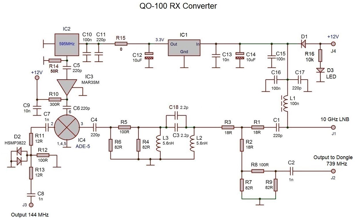
OSCAR 100 Kits
http://transverters-store.com/qo100_inbox.htm
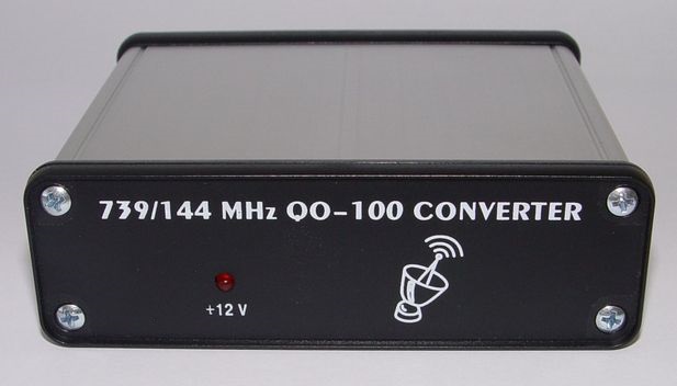
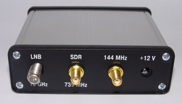
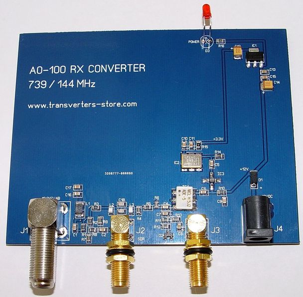
This converter was designed to use it to receive the signals from modern QO-100 or Es’hail-2 amateur radio satellite. This satellite was put on the geostationary orbit at position 25.9°E. Its uplink frequency is on 2.4 GHz band and downlink frequency is on the 10 GHz band. So the low cost Satellite TV dish (60cm min) with 10 GHz (LO 9.75 GHz) modified LNB can be used to receive its signals. Modification of LNB represents a replacing of 25.000 MHz crystal in LO of LNB to the high stability TCXO of 25.000 MHz. Not all LNB will work there. It needs the modern LNB with PLL synthesizer in its LO.
YOU CAN BUY 10 GHZ MODIFIED SAT TV LNB here
Using this converter along with the low cost Dongle SDR tuned around 739 MHz or 2 meters band receiver tuned in a range of 144.550 – 144.800 MHz you can receive the signals of narrow band transponder of this satellite.
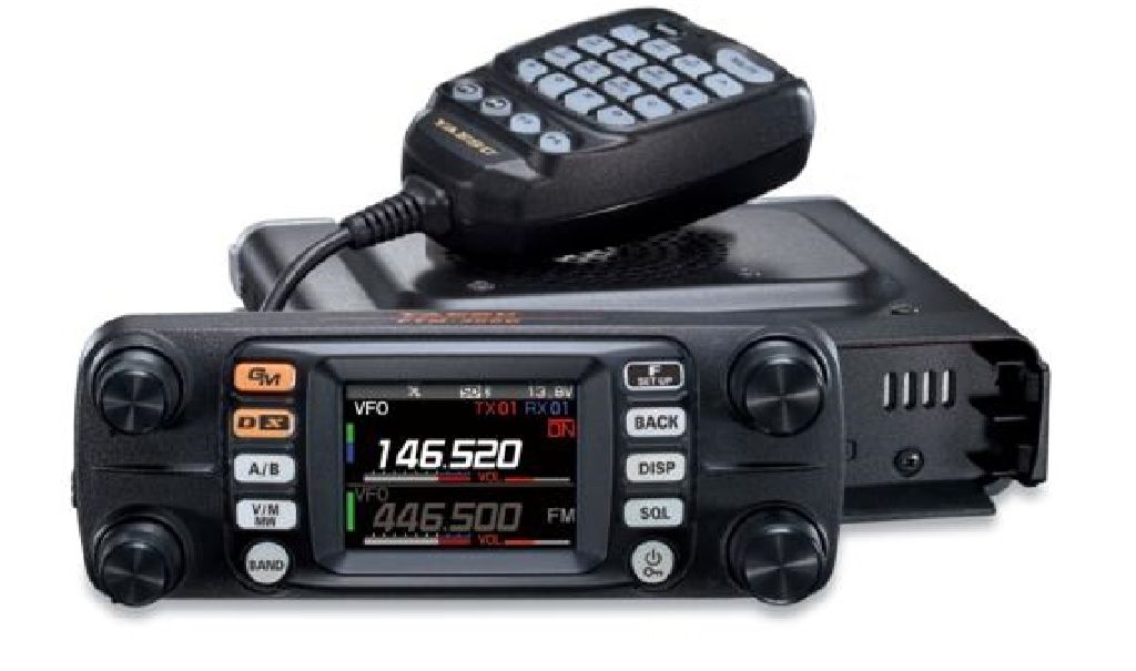
Check out this new baby!
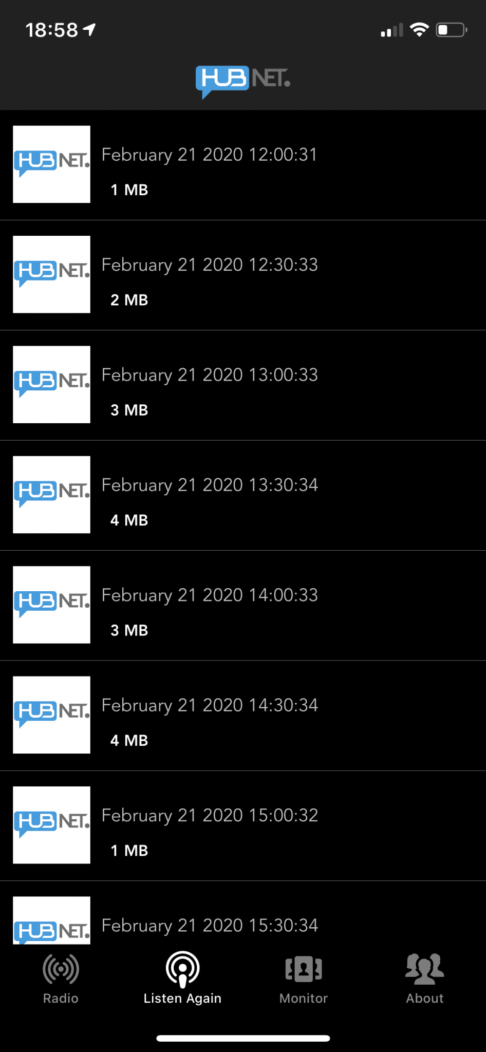
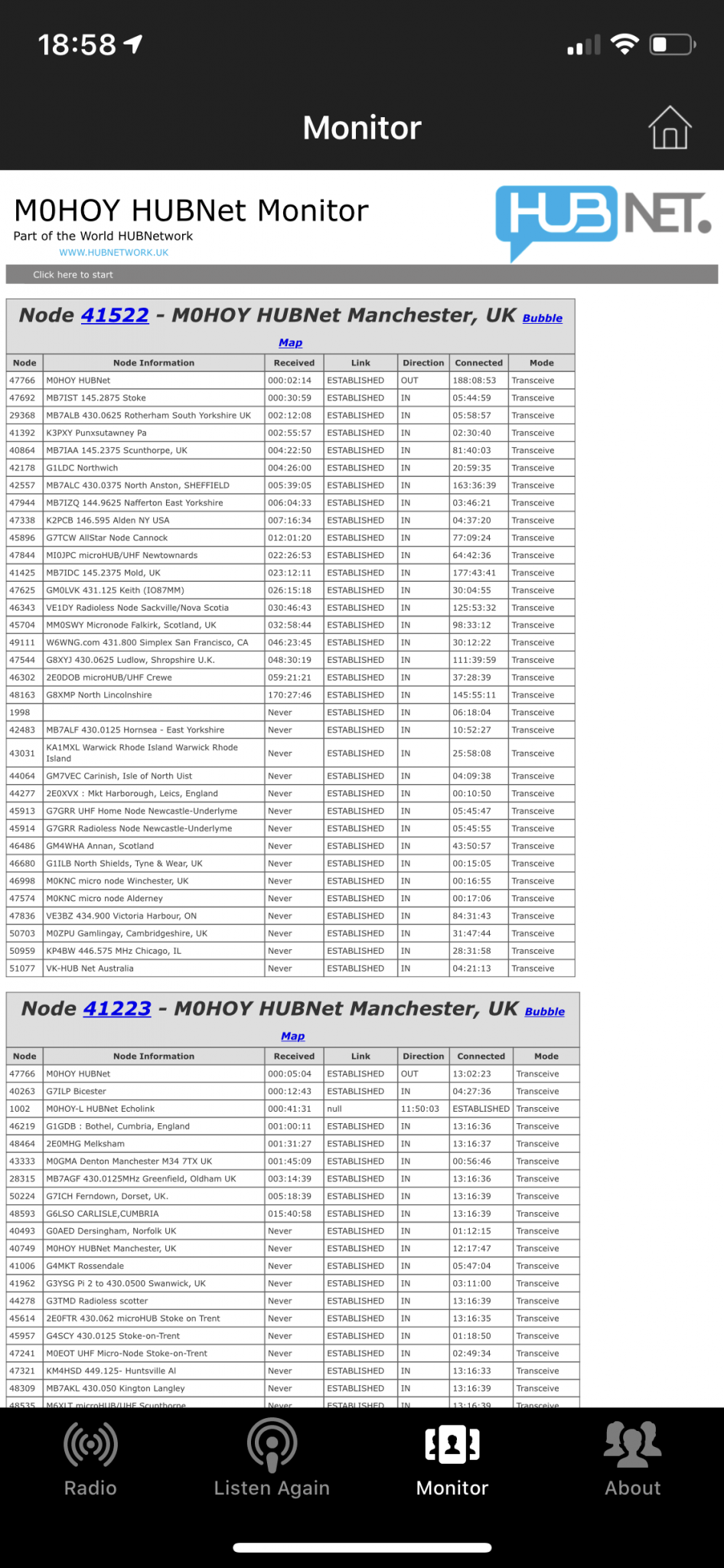
News! Matt M0DQW has now written a app for iPhone and Andriod phones. Search Google Play Store for HUBNET UK or the App store on Apple.

Hello all. Well we did a test on GB3SJ while on the midcars clubnet on Tuesday the 7th Jan 2020 linking it to GB7DJ (DMR) and GB7SJ(Fusion Digital) Here is a link to the recording.
GB7SJ in now Analog only on FM Allstar node number 41360 connected to the NWAG North West Allstar Group 24/7. This was done to allow Allstar and FM user access to a local ish only repeater as the GB3SJ repeater on HUBNET is now so busy most of the time.
March 2020
Between 7am-7pm 7 Days a week GB7YZ and GB7SJ will be linked to NWL (Northwest Link DMR Talkgroup 23520) Your radio will need to be on DN on Fusion to be heard on the DMR
GB7SJ is now auto FM/digital mode.
GB7YZ UHF Fusion is now Live and linked 24/7 to YSF GB7SJ reflector March 2019
See Blog from Keith 2E0ISK https://www.mr-badger.co.uk/operation-victor-whisky/
Another interesting Blog from Keith https://www.mr-badger.co.uk/glib-glob-and-squawk/
GB3SJ VHF Allstar (47000) linked to HUBNet is on air. Feb 2018
HUBFest Meetup on the 27th May – 31st May 2020 Come and join us on-site £2 for a day visitor (Site fee not us!)
GB7DJ Is Now Live !! Club Callsign is M0XSJ
GB7SJ has had a frequency change. NOW linked to GB7YZ
| Callsign | Band | Chan | Output | RX1 | CTCSS | Mode |
| GB7YZ | 70cm | DVU38 | 439.4750 | 430.4750 | Fusion YSF GB7SJ | |
| GB7SJ | 70cm | RB07 | 433.1750 | 434.7750 | 103.5Hz | Analog/Fusion |
| GB3SJ | 2m | RV55 | 145.6875 | 145.0875 | 103.5Hz | Analog/Allstar Linked |
| GB7DJ | 70cm | DVU53 | 439.6625 | 430.6625 | DMR/3 | DMR |
GB7DJ up and running on the DMR Brandmeister Network
GB7SJ is used for the MIDCARS Net every Tuesday evening at 8-9pm
“Mid Cheshire Amateur Radio Society “MIDCARS“” Club Net every Tuesday evenings from 8-9pm on GB3SJ and ALLSTAR node 47000
Welcome to GB7SJ repeater website.
Repeater Output is on 433.1750mhz and input is 434.7750mhz (+1.6mhz) with 103.5hz CTCSS tone.
If you want to use GB7SJ repeater on Fusion digital please wait for the carrier to drop before transmitting on DN or VW (Fusion Digital modes)
More information can be found here in the future regarding codes etc for internet link this repeater.
GB7SJ is now linked to GB7YZ in Mold in Fusion mode.
BIG THANKS to G7RPG for helping me make that happen!